How to Choose A Tank Blanketing Valve
WHAT TO CONSIDER WHEN SELECTING A TANK PAD OR DEPAD REGULATOR
Choosing the Tank Blanketing Valve for Your System
It is extremely important to choose a tank blanketing system suitable to handle the required inlet pressure, flow, and set-point for your specific application. Maintaining the vapor pressure in the tank is key to process safety and product quality. The vapor space in process tanks can be affected in a variety of ways: When pumping media in and out; when temperature of the tank contents changes; or when air or moisture enters the tank and vapors escape the tank. Most tanks are not perfectly sealed enclosures and as a result, air and moisture can enter the tank and affect the tank contents. Having the right tank pad/de-pad valve will help keep the tank pressure at desired setpoint during these transitions.
The proper valve for a system may be in the form of a direct-operated regulator or a pilot-operated regulator. You may need a pressure reducing valve / “padding” regulator, a back pressure valve / “de-padding” regulator, or BOTH for your system. Valve function, operation, material compatibility and size are all factors to consider when choosing a tank blanketing system. Jordan Valve is here to help you choose the optimal regulator for your application.
Direct-Operated or Pilot-Operated Tank Blanket Regulator. What is the Difference?
Direct-operated regulators respond directly to variations in the controlled process pressure and adjust to provide the necessary flow and pressure to satisfy the system set-point. Pilot-operated regulators have a higher gain and an external sensing line to improve regulator sensitivity for higher accuracy.
Direct-operated tank blanketing valves are sometimes called self-operated valves and are a good choice for those wanting low initial cost, easy maintenance, and reliable low pressure gas control. Jordan Valve direct-operated tank blanketing valves offer:
- low initial cost and easier installation and maintenance
- faster response for reliable tank pad pressure control
- Smaller sizes can maintain low set-points in some conditions when installed following the steps outlined in the installation manual.
Jordan Valve direct-operated models may have internal or external sensing/registration depending on size:
- Direct-operated blanketing valves in smaller sizes (usually under 1-1/2 inch) have internal registration/sensing.
- Larger direct-operated models (1 ½ to 4 inches) use external sensing, providing greater accuracy as long as the installation procedure is followed. (e.g sensing line is straight and short; full size piping is used; etc.).
Pilot operated tank blanketing valves are a good choice for applications requiring higher flows or higher precision and are worth the higher initial capital outlay. Jordan Valve pilot-operated tank blanketing valves offer:
- greater accuracy than self-operated valves
- extremely fast lock-up, reduced valve droop
- can more accurately control to lower pressure set-points
Jordan Valve pilot-operated tank blanketing models all use external registration / sensing.
For more information about the difference between direct and pilot operated regulators, visit the Fluid Controls Institute (FCI) education website.
Your system may need a tank pad or depad regulator or both
Pad is the portion of the process that provides blanket gas into the tank’s vapor space, maintaining its pressure or ‘gas blanket.’ Depad functions to remove gas from the tank’s vapor space in cases where the pressure in the gas space increases. Pad and depad processes are also called tank “make-up” and “vent.” Two-sided blanketing systems use pad and depad regulators working together to maintain the vapor space pressure. One-sided systems typically use pilot-regulated tank padding valves with a conservation vent or emergency vent.
Pressure reducing regulators are used for tank make-up/ padding. Back pressure regulators are used for tank venting/ depad. Tank blanketing valves often need to control at very low pressure down to inches of water column.
How to use API-2000 to choose the right size?
When choosing a tank blanketing regulator for venting low pressure petroleum storage tanks, American Petroleum Institute’s API 2000 Standard guides engineers in sizing valves. Tank pressure set-point, pump in rate, pump out rate, and tank capacity are the main factors for determining valve size. The tank blanketing set-point is determined by the tank manufacturer or operator. The capacity requirement is determined by the following factors:
- Inbreathing due to product movement out of the tank (Q-displacement)
- Inbreathing or outbreathing due to contraction or expansion of the vapors due to weather or process temperature changes (Q-thermal)
- Geographical location
- Tank insulation
API calculations will help determine the flow you need for your system. From there, download our Jordan Valve Tank Blanketing Quick Reference Guide for more details about flow capacity and size information.
About Tank Blanketing Valve Installation
Proper installation of the blanketing regulator is just as important as selecting the right size in optimizing valve performance for the best tank padding operation. Following manufacturer’s instructions for installation of the regulator and sensing line, also referred to as the control line or impulse line, is the best way to ensure maximum performance in a blanketing regulator.


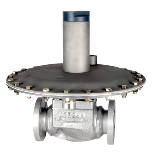
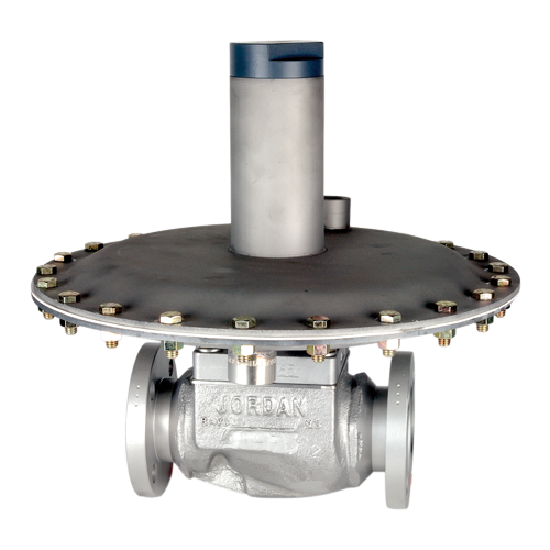
 Mark 508 Series Direct Operated Tank De-pad Regulator
  Mark 608 Series Direct Operated Tank Padding Regulator
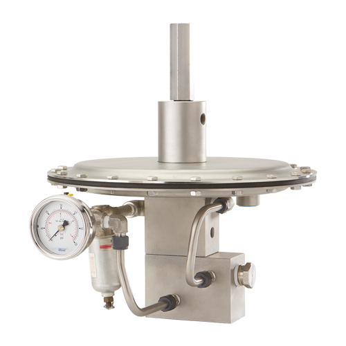
  Mark 695 Series (3/4″ – 1″) Piloted Tank Padding Regulator
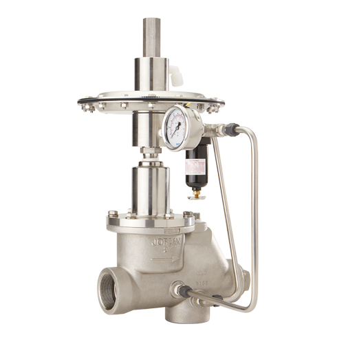
  Mark 695 Series – 2″ Internal Piloted Tank Padding Regulator