


Ideal Installation of a PRV in a Steam System
Following the steps in the process below will maximize the performance and service life of your pressure reducing valve in critical services, especially steam.
Installation
- To protect the valve from grit, scale, thread chips and other foreign matter, ALL pipelines and piping components should be blown out and thoroughly cleaned before the installation process begins.
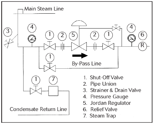
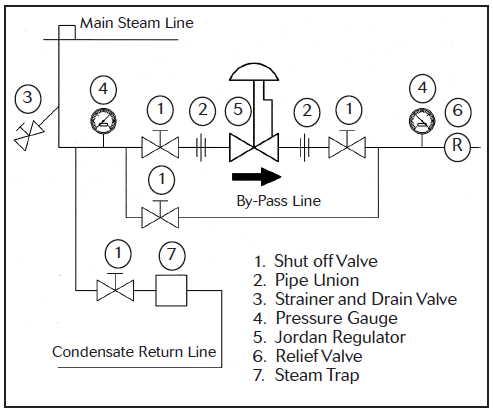
- Shutoff valves, pressure gauges and by-pass piping should be installed as indicated in the Ideal Installation Schematic to provide easier adjustment, operation, and testing.
- A line strainer should be installed on the inlet side of the valve to protect it from grit, scale and other foreign matter. A 0.033 perforated screen is usually suitable for this purpose. Line strainers are available from Jordan Valve.
- For best control, 3’ 0” straight sections of pipe should be installed on either side of the valve.
- In preparing threaded pipe connections, care should be exercised to prevent pipe-sealing compound from getting into the pipelines. Pipe-sealing compound should be used sparingly, leaving the two end threads clean. Jordan uses, and recommends, thread sealer Teflon ribbon.
- The flow arrow on the valve body must be pointed in the direction of flow. Ideally, the valve should be installed in the highest horizontal line of piping to provide drainage for inlet and outlet piping, to prevent water hammer, and to obtain faster response.
- If possible, install a relief valve downstream from the valve. Set at 15 psi above the control point of the valve.
- In hot vapor lines, upstream and downstream piping near the valve should be insulated to minimize condensation.
- In gas service, if the control pressure (downstream) is 25% of the inlet pressure or less, expand the outlet piping at least one pipe size. A standard tapered expander connected to the outlet of the valve is recommended.
10. Where surges are severe, a piping accumulator is recommended.
11. On steam control applications, install a steam trap with sufficient capacity to drain the coil or condenser. Be sure to have a good fall to the trap, and no back pressure. Best control is maintained if the coil or condenser is kept dry.
Control Line
A control line is required in externally-sensed pressure regulating valves. This applies to pilot-operated regulators and most larger (2-1/2″ +) diameter self-operated regulators. Adherence to the following steps will ensure proper installation of the control line and maximum performance of your regulator.
A control line must be installed as follows:
- Connect one end of a 1/4” control line to the 1/4” NPT tapped opening in the underside of the lower spring housing.
- Connect the other end in a straight run of pipe 3 to 5 feet downstream of the valve.
- DO NOT locate the control line tap in an elbow, swage, or other changes in configuration of the pipeline where turbulence or abnormal velocities may occur.
- DO NOT locate the control line tap in a vessel, such as a deaerator located immediately downstream of the valve instead locate the tap in the pipeline leading to the vessel.
- The control line should be sloped away from the valve.
- Install a shut-off valve (not a needle valve) in the control line.
- Install a pressure gauge in the control line or near the inlet of the valve to aid in setting the valve and checking for inlet pressure during maintenance procedures. (There is a ¼” NPT tapped opening in the lower bonnet.)
Please contact your local representative with any questions. You can find your rep here.